My first step in engine dissasembly, once I had the location setup and was prepared for my expedition, was to take off the intake and cam covers to send to Dave Shaeffer. The Workshop manuals provide little assistance here - the best I could find was "remove cam covers". So.. Back upstairs, I found a very useful document by David Chamberland on Intake Removal (available from the 928OC website) as well as some helpful pages on Cam Cover removal on V1UhOh's website.
|
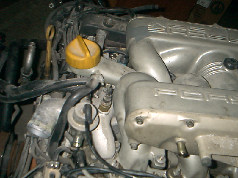
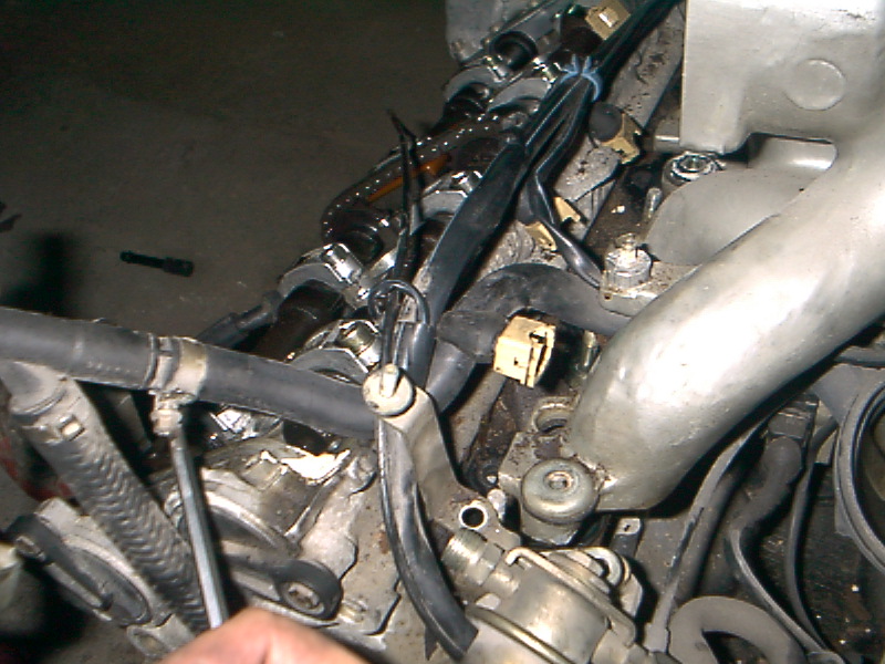
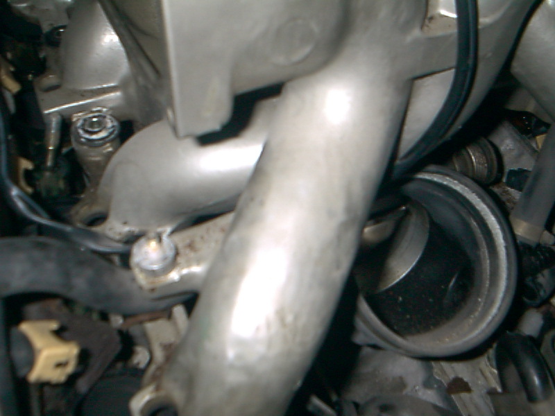
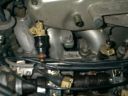
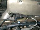
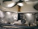
The first thing I did was remove the intake jet pump.
|

|
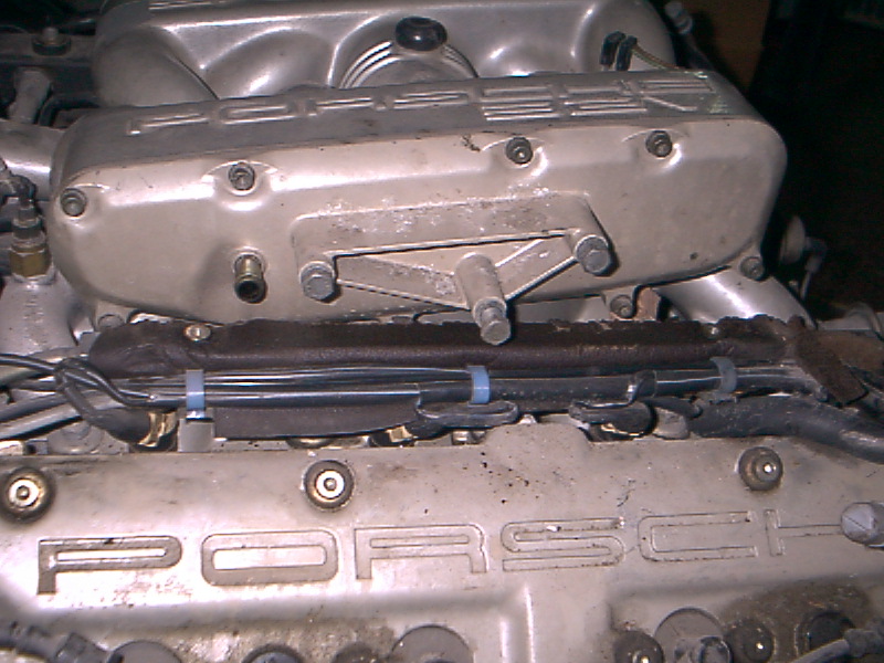
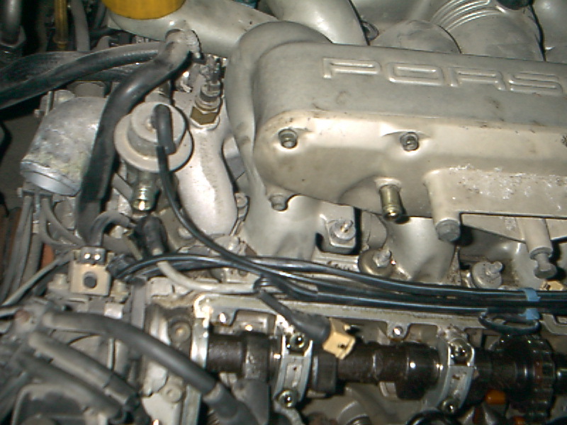
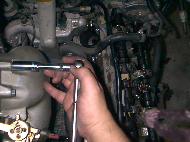
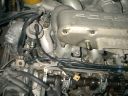
I then removed the bolts that hold on the fuel rail covers.
|
|
|
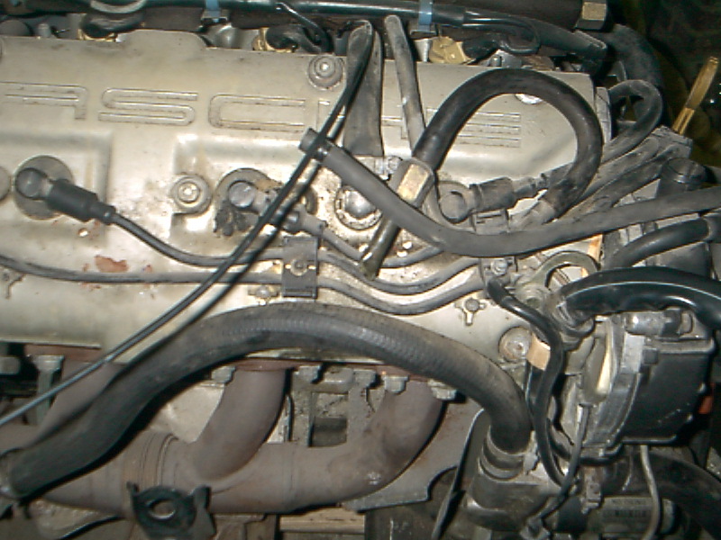
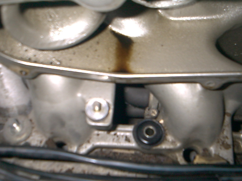
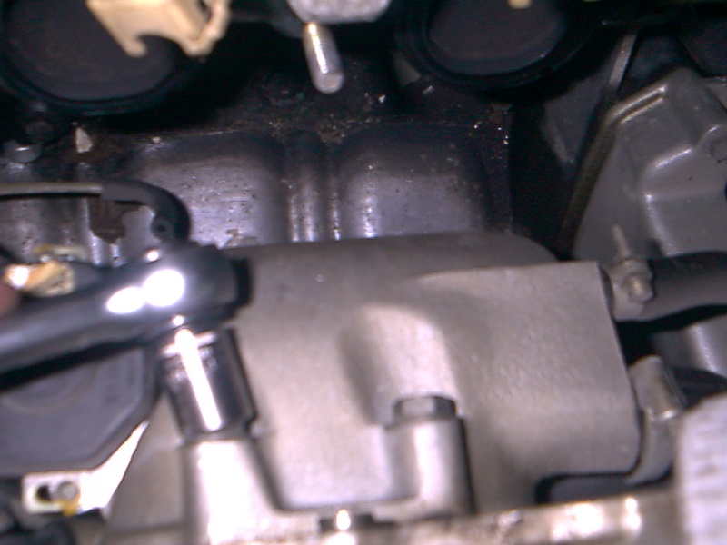
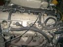
Underneath the fuel rail cover on the driver's side, the insulation looked fairly intact although it was starting to come apart near the ends.
|
|
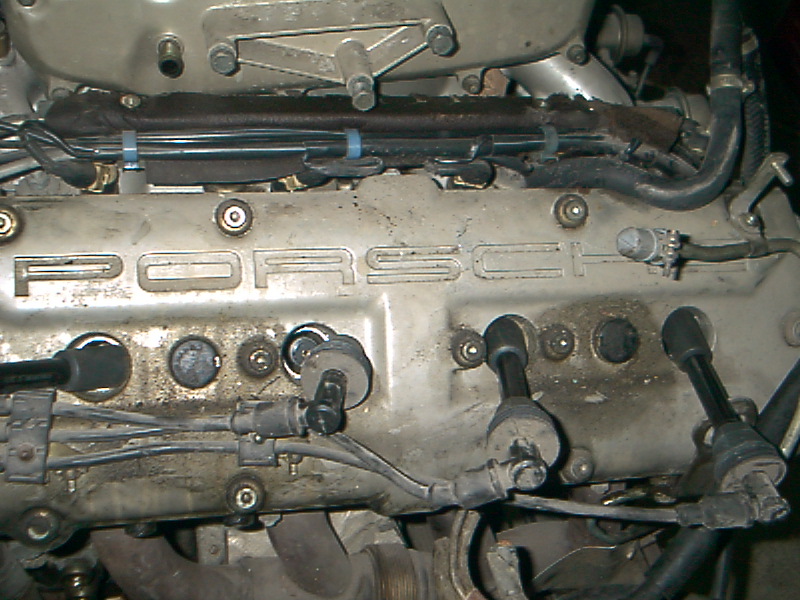
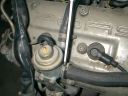
Since it seemed that I would be able to access the fuel rails more easily if I removed the cam covers, I decided to remove the cam covers before proceeding further. The first step here was the remove the spark plug wires which were very dry and crumbly.
|
|
|
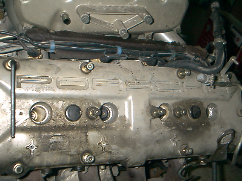
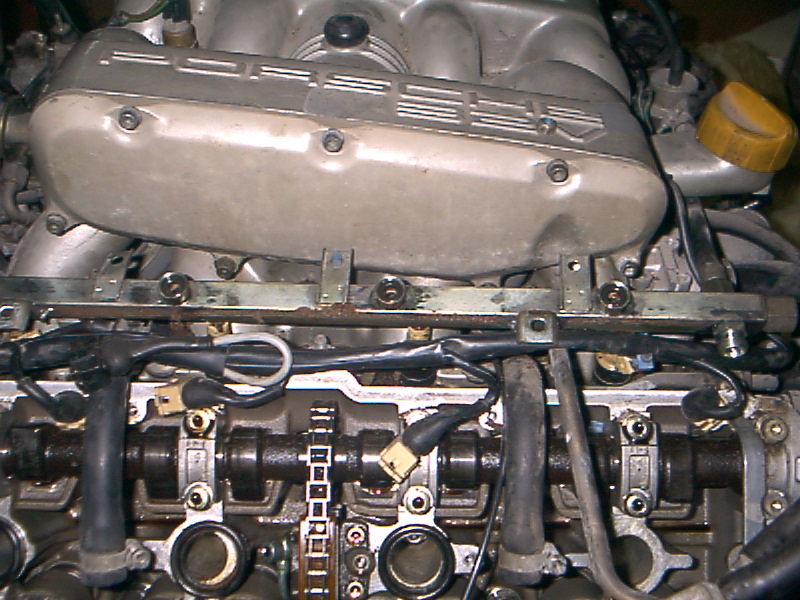
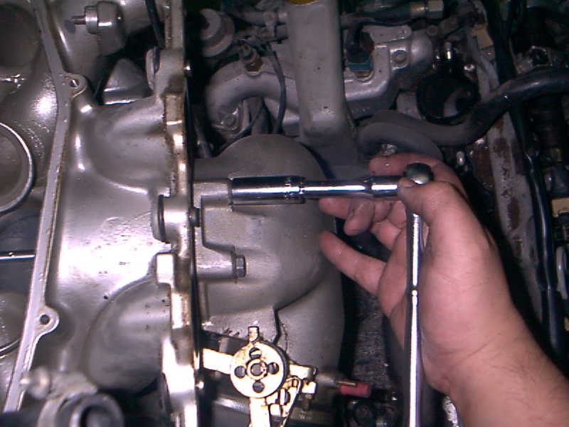
I then removed all of the bolts holding the cam covers on. I started with the outermost bolts, loosening each about 1/2 turn and working my way to the center.
|
|
I also had to loosen the screws holding the engine lift point. After that I was able to take the driver's side cam cover off with very little effort. (I used a large screwdriver on a raised corner to get it started - thanks, Tony!)
|
|
|
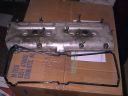
Here's the driver's side Cam Cover and gasket looking a bit lonely.
|
|
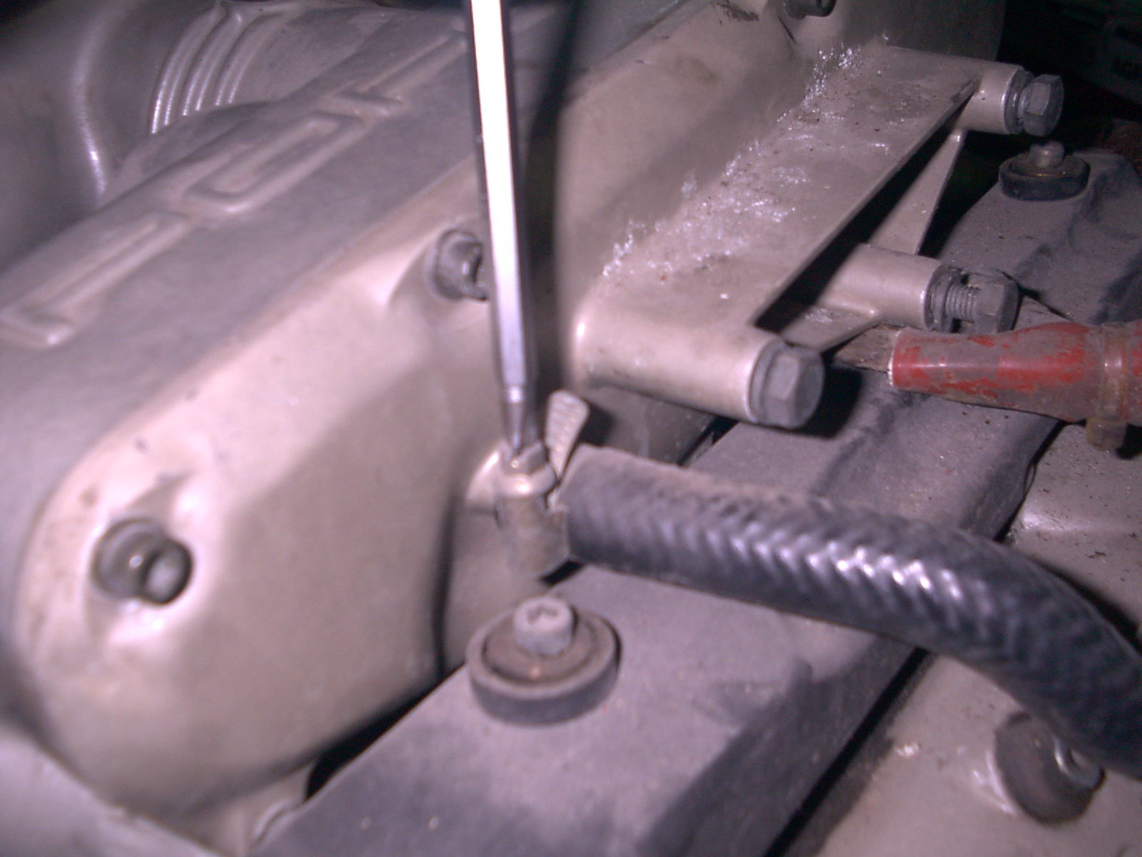
Back to the fuel rails.. The fuel rail is attached in the front and the back to the fuel lines. I didn't have the right size flare wrench for these but was able to counterhold and open with a pair of adjustable wrenches.
|
|
|
This is the front driver's side fuel line after its opened. You can't actually tell because of the crappy photographer.
|
|
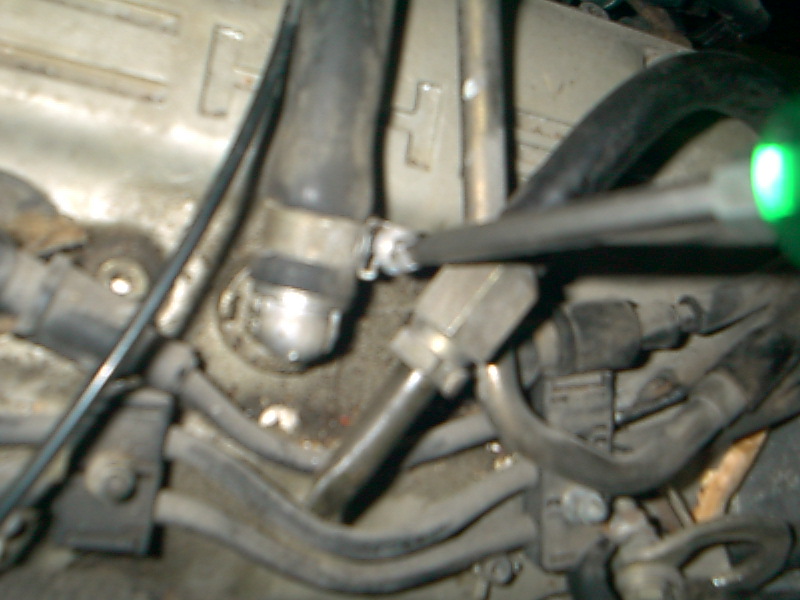
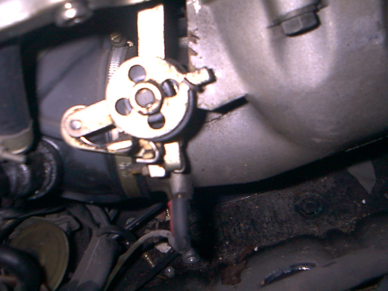
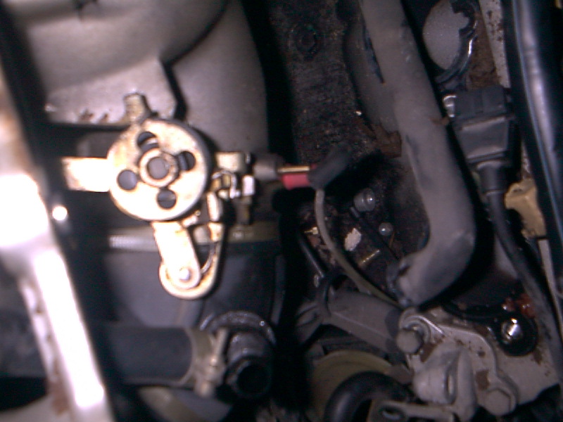
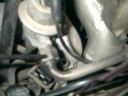
This is the rear fuel line, driver's side. Where it attaches to the fuel pressure damper.
|

|
|
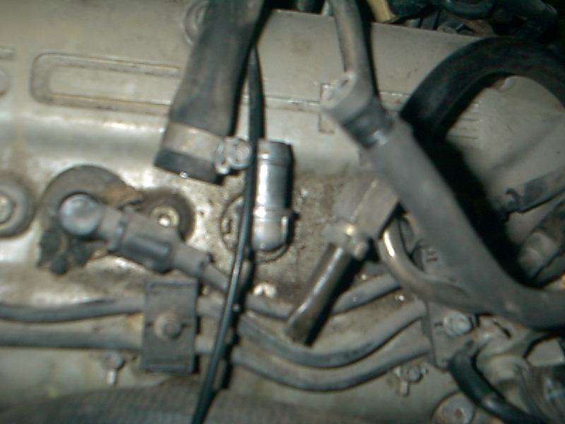
Disconnected.
|
|
Next I detached all four of the injector cables. This was a real pain without the special Bosch tool. I highly recommend coughing up the $20 if you plan to do much work on your 928..
|
|
|
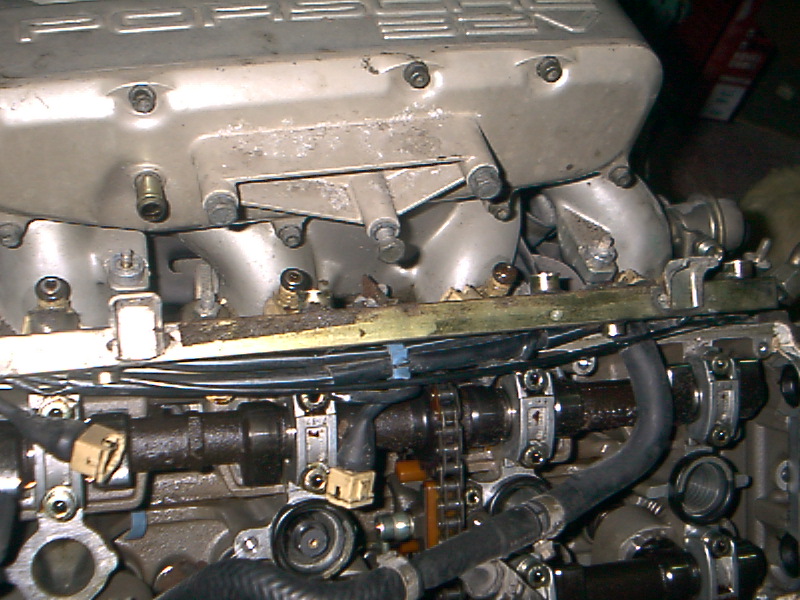
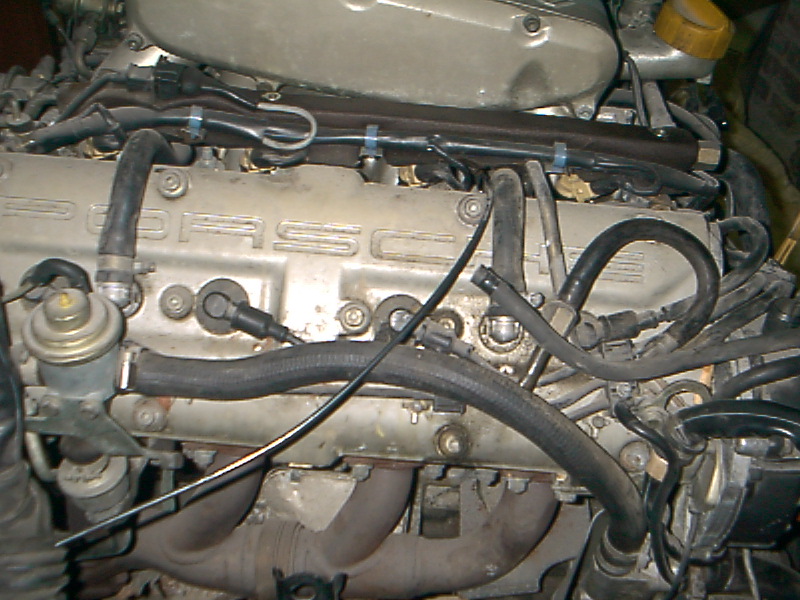
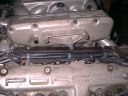
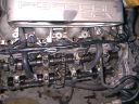
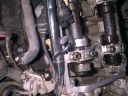
Here's a photo of all four - you'll notice, somewhere along the line, I removed all the insulation from the fuel rail. I should also point out that the cams really should be covered so that little bits of grit and dirt don't fall in them. I didn't do so because I'm planning on taking everything apart and cleaning it all. I probably should have covered them anyway.
|
|
Here's another very blurry picture of a retaining clip partially on an injector. The autofocus on this camera leaves something to be desired.
|
|
|
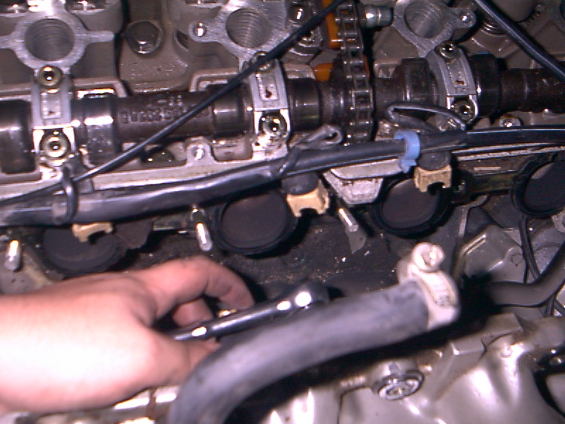
After removing the retaining clips, using the aformentioned very large screwdriver and an old towel, I pried the fuel rail off of the injectors, slowly working my way along the fuel rail until I had worked it off of all four injectors.
|
|
I then proceeded to pull the injectors out - all but one of them came out really easily, indicating that the gaskets are old and should probably be replaced. I was actually able to pull out all four on the driver's side by hand.
|
|
|
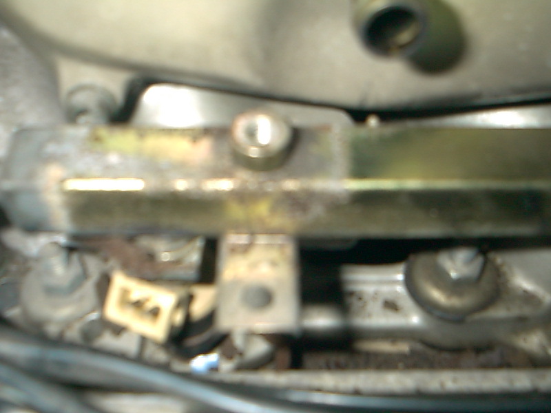
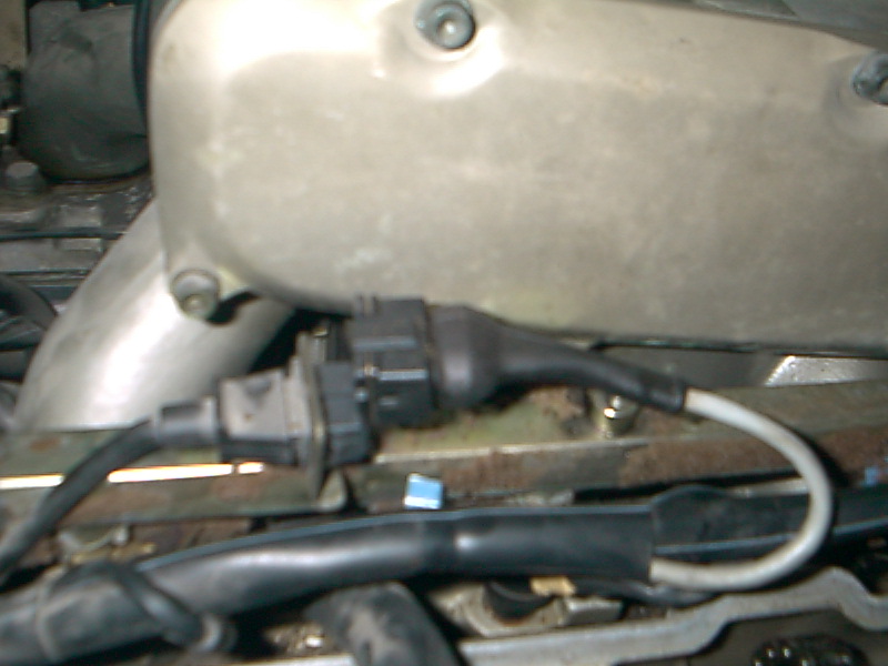
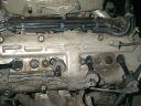
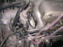
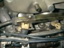
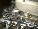
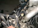
I don't remember the significance of this picture.. It may have been to remind me of the knock sensor connector (visible in the lower left corner) Also I removed a hose..
|

|
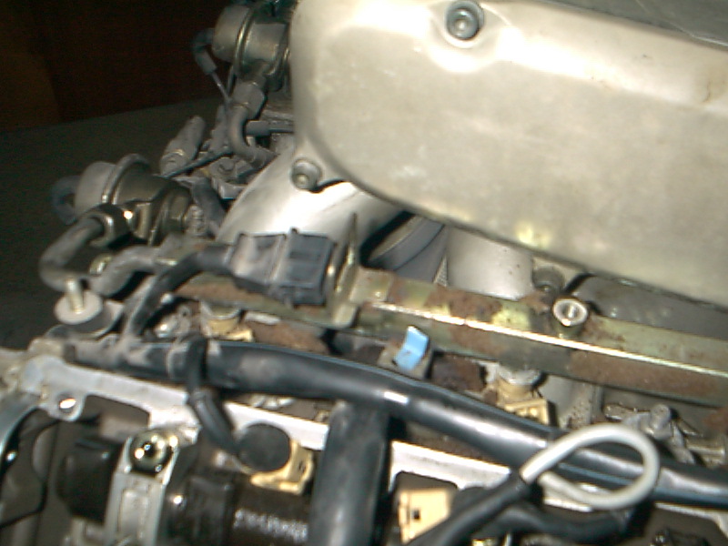
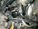
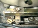
Ditto for this one..
|

|
|
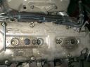
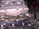
Another picture of the same area. You can see the cams are getting all dusty.. Next time I'll remember to cover them.
|
|
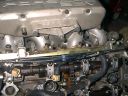
Next I removed the fuel rail cover on the passenger side.
|
|
|
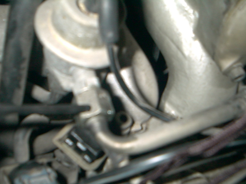
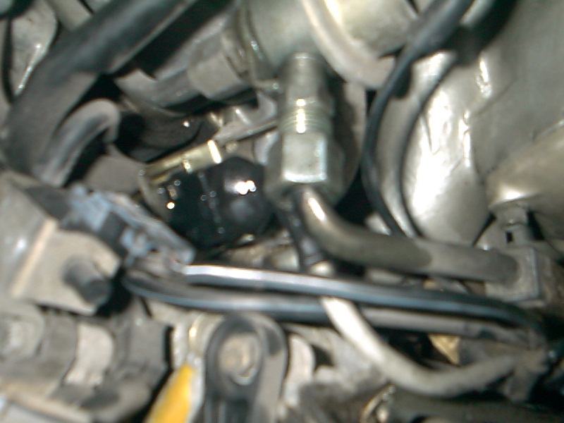
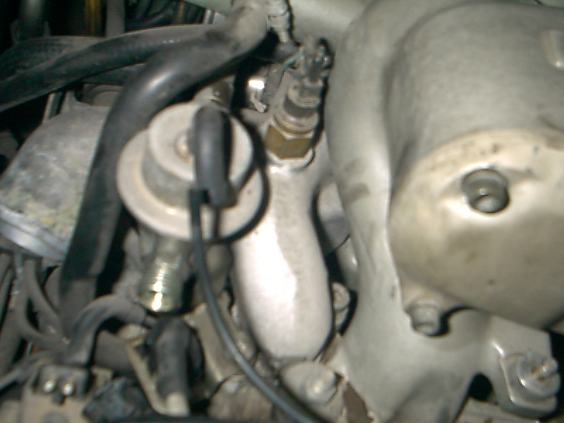
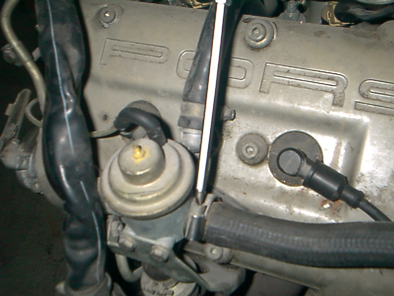
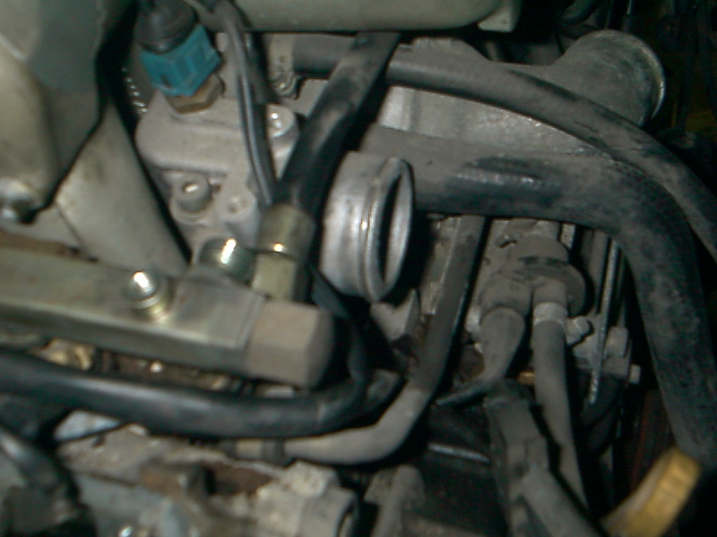
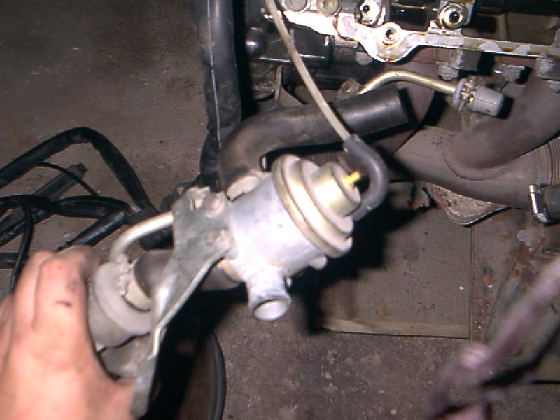
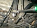
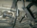
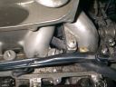
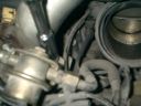
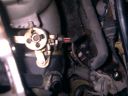
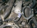
I don't know what this hose is called.. Its attached to a thing that I believe is a vacuum thingie.
Update: I'm told this is the diverter valve which sends air from airpump. The large hose goes to the airpump.
|
|
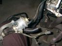
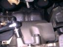
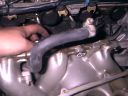
After removing the previous hose, I removed the first of two breather hoses.
|
|
|
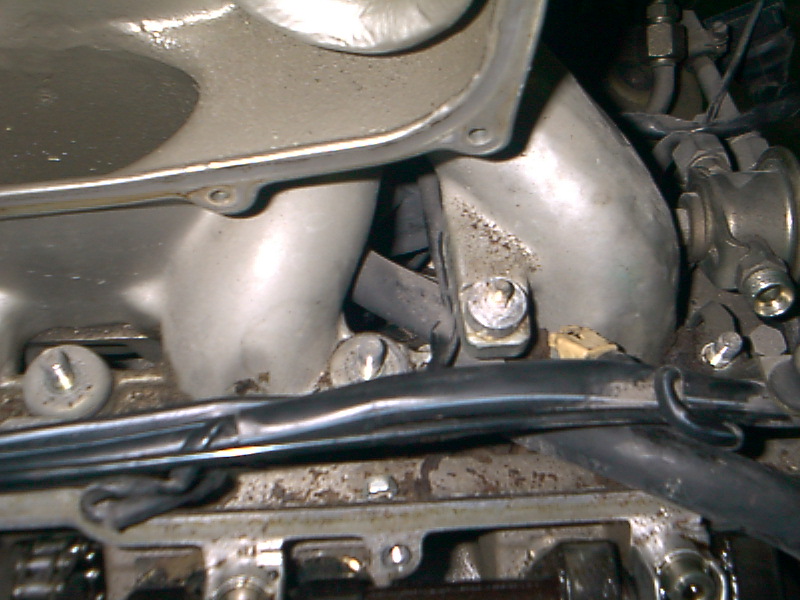
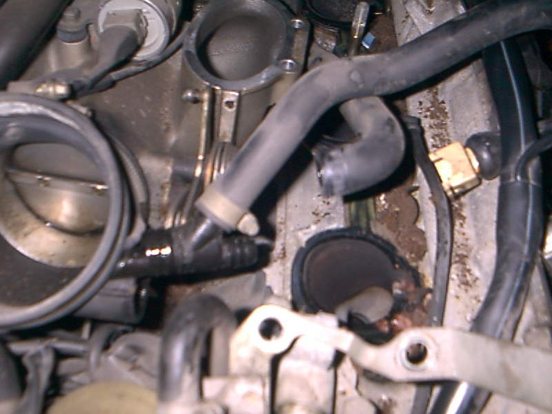
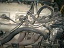
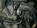
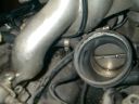
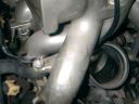
This is a picture of two unknown mystery hoses. One that looks like it was cut off by someone. The hose in question is the one underneath the other hoses with the brass fitting on the end. The other one is the one above it.
Update: I'm told the hose with the brass connector, if my note is correct, is the fuel feed from tank to charcoal cannister.
|
|
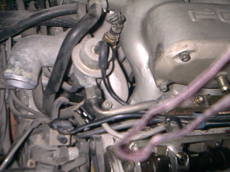
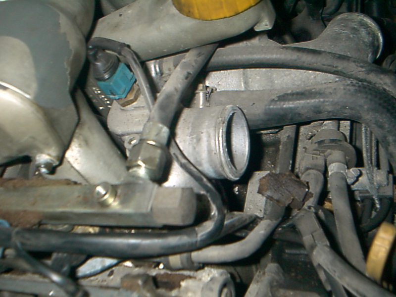
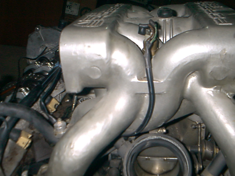
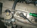
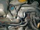
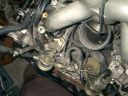
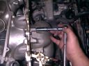
Here's another mystery hose - this is the very thin hose (also visible in the last picture) that is coming from the front of the intak and ending abruptly above the exhaust manifold.
Update: I'm told that this goes to the Charcoal Cannister Purge Valve.
|
|
|
Finally taking off the second breather hose.
|
|
Here it is removed. After that I removed the Cam Cover but didn't document since it is the same as the driver's side.
|
|
|
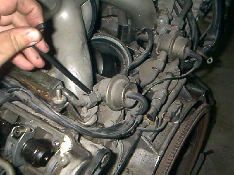
Next, the front a rear fuel line fittings.
|
|
Here's the front one removed.
|
|
|
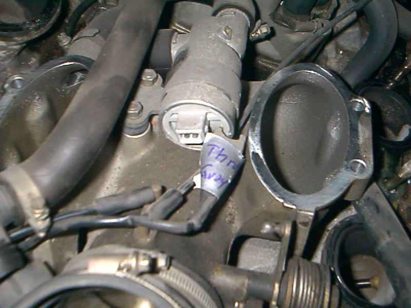
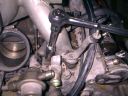
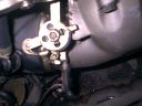
In order to get the Cam Cover off, I had to take this piece off - I really wish I could remember what its called but I'm too lazy to look it up right now.
|
|
Another picture.
|

|
|
Next I detached the knock sensor connector. That Bosch tool would be really handy!
|
|
Here it is removed.
|
|
|
I then removed the fuel rail, same as the driver's side. And then the injectors - two of the injectors on this side were very had to remove. On one of them I used my large screwdriver and towel.
|
|
In order to access the nuts holding the manifold on, I had to remove the side covers. I actually spent about 20 minutes trying to get at one bolt before the light dawned on my pointy head..
|
|
|
Nut and washer removed (there's 10 in all, 5 per side)
|
|
More..
|
|
|
Here's another view, all nuts removed.
|
|
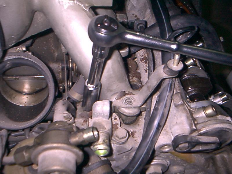
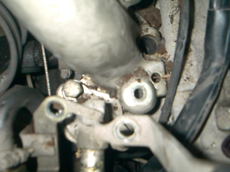
In order to lift the manifold, I had to remove the mount for the air intake box and the fuel regulator.
|
|
|
Here it is removed.
|

|
On the driver's side I had to remove the fuel damper as well.
|
|
|
Removed.
|
|
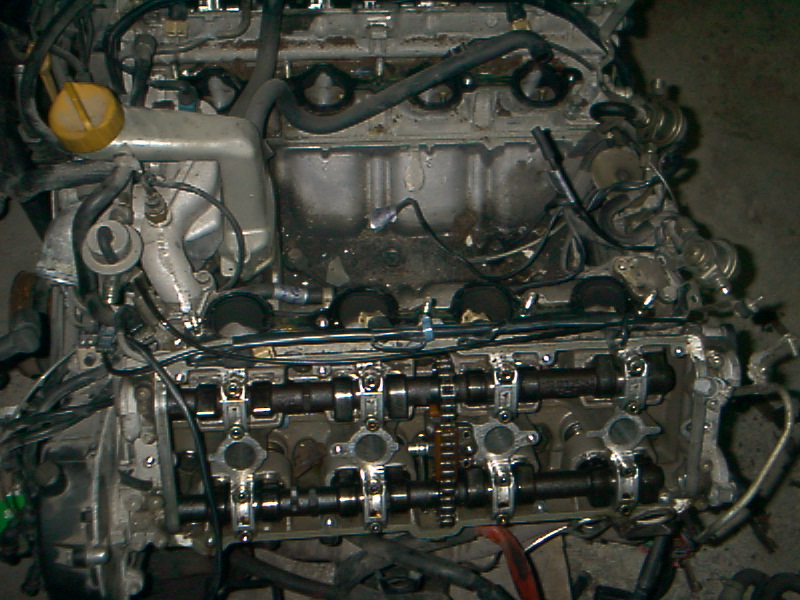
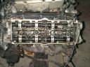
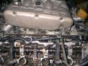
Once all the screws were out, the intake lifted up very easily. As you can see, I really should have covered the cams.
|
|
|
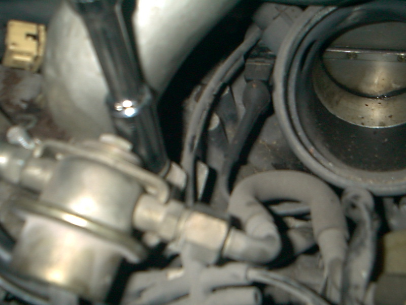
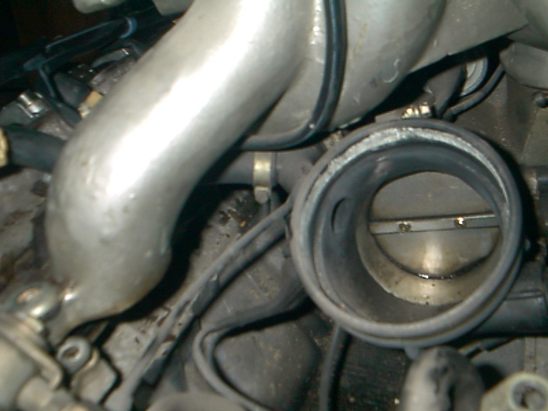
With the intake lifted a couple inches, you can see into the "V" underneath. The throttle body and lower part of the MAF are attached to the intake and there are various connections to them preventing removal of the intake at this point.
|
|
I next removed this large hose/Y-connector from the MAF (this isn't really the MAF - its just the elbow the MAF connects to but I don't know the right name for it)
|
|
|
Here's that hose again, no longer connected to the MAF elbow. I disconnected it from another hose that runs to the front of the engine.
|
|
Here it is disconnected.
|
|
|
This is the inderside of the intake, showing the throttle body and MAF elbow from the side.
|
|
I then removed the pair of electrical plugs from the bottom of the throttle body.
|
|
|
And the pair of electrical plugs at the top of the manifold.
|

|
I'm not sure why this picture is here.
|
|
|
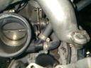
Holding the intake on its side, I unbolted the throttle body.
|

|
Here's a wider shot of same.
|
|
|
The other side.
|
|
Another angle. These pictures were kind of hard to take without a helper so I took several in hopes that at least one would be helpful.
|

|
|
Yet another..
|
|
Here's the throttle body disconnected from the intake.
|

|
|
Another Bosch connector removed - you'll notice, at this point I got smart and started labelling both sides of removed connectors.
|
|
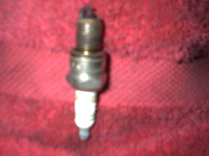
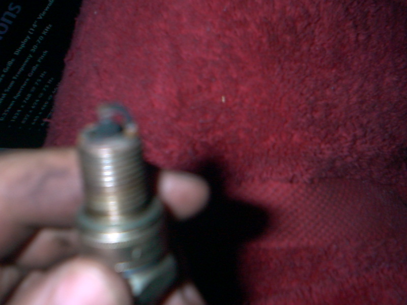
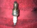
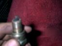
Here's one of the spark plugs. The tip is almost black indicating the fuel mixture was probably too rich.
|
|
|
|
|
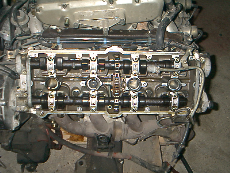
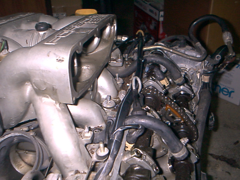
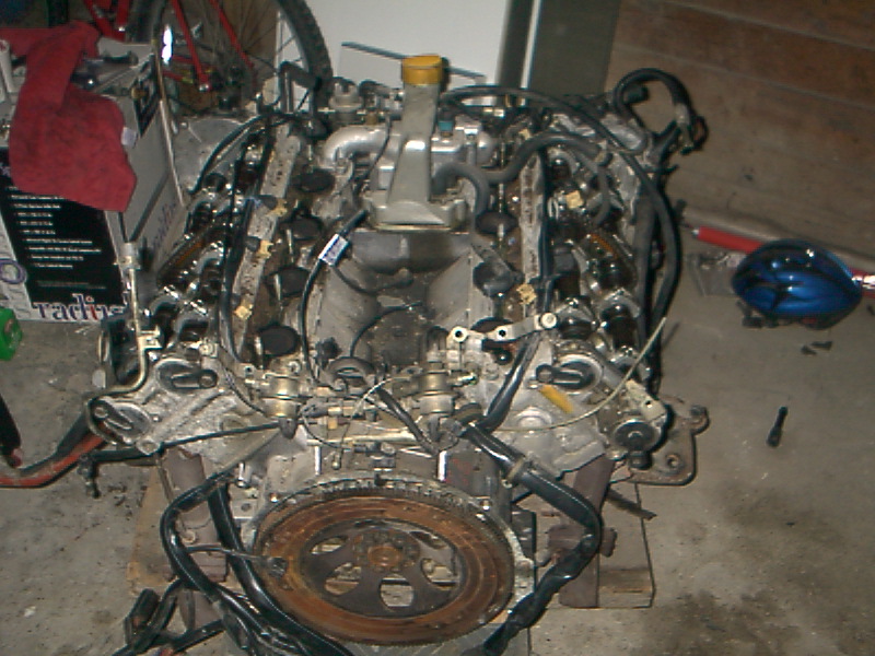
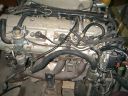
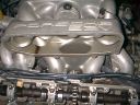
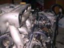
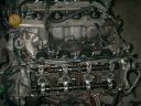
The engine is much shorter with the intake, cam covers and throttle body removed!
|
|
|
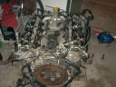
One last picture..
|
|
|
|